Meet the real-world challenge: Help a model relief team assemble a temporary shelter quickly from common materials.
Grade 5 · 3D Printing · Lesson 17
Emergency Shelter Connector Kit
Engineer reusable joints that turn simple sheets and rods into a strong model shelter.
Time3 × 60 minutes + adult fabricationTeamsTeams of 3–4EquipmentBambu P1S fleet + basic sheet materials
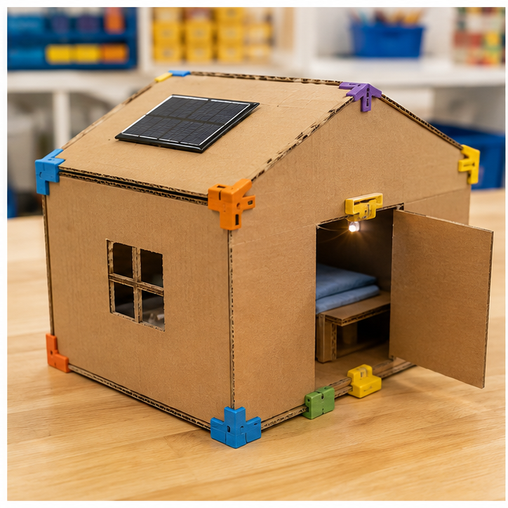
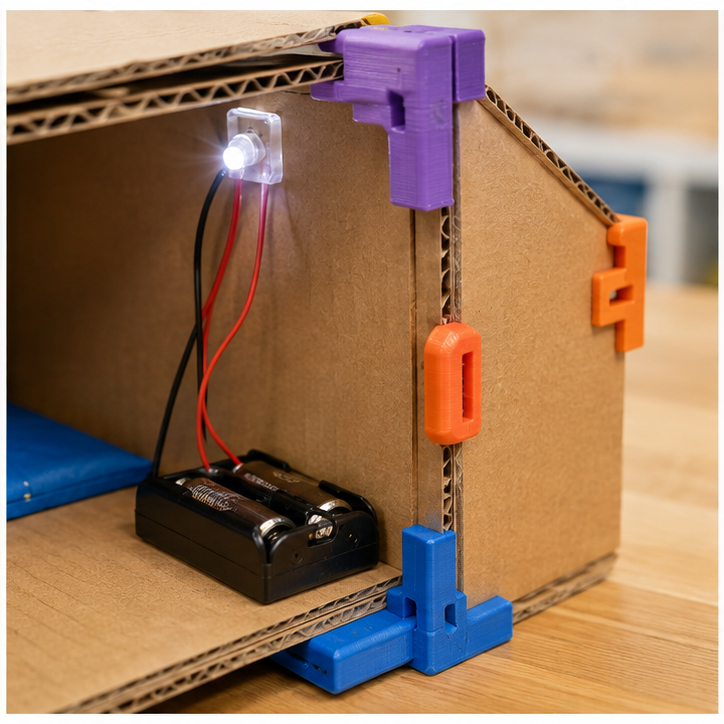
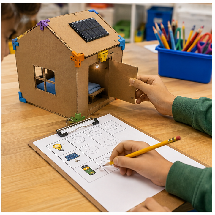
Project inspiration · 3 images
See, build, and test
Use these images to understand the kind of making, details, and testing involved. They are inspiration—not designs students must copy.
Student quick guide
What are we doing?
Choose materials, build the control system, and connect the rod sizes, panel angles, and structural loads to the a reusable family of printed connectors.
Test the same way each time, study the evidence, and improve one part.
For teachers
Engineering standards
This shows how the lesson connects to the national NGSS engineering standards and what student work you can collect.
Assessed
3-5-ETS1-1
Teams define who needs the emergency shelter connector kit and set measurable performance, safety, material, and time limits.
What students show: User-centered problem statement with criteria and constraints.Practiced
3-5-ETS1-2
Teams compare at least two circuit, code, or enclosure ideas against the success criteria.
What students show: Labeled system diagrams and a recorded design choice.Assessed
3-5-ETS1-3
Teams run a repeatable test—apply the same fan distance and roof load to each connector design—then change one variable and retest.
What students show: Test table, code or build revision, and evidence-based explanation.Materials
- Cardboard, paper, craft sticks, tape, reusable building pieces, and student-proposed materials
- Project platform: Bambu P1S fleet + basic sheet materials
- Breadboard, paper-circuit supplies, or low-voltage power when needed
- rod sizes, panel angles, and structural loads input component or student-designed substitute
- a reusable family of printed connectors output component or student-designed substitute
- LEDs, resistors, jumper wires, copper tape, switches, and clips as needed
- 3D Printing materials for an optional case, sign, mount, or model
- Computer with approved coding or simulation tools when needed
- Planning sheet, ruler, and test-data table
Teacher preparation
- Build and test one possible reference solution without making it the required design.
- Prepare a basic-materials table plus optional electronics and fabrication stations.
- If coding is used, prepare a starter option for parametric CAD dimensions and part variants; students may propose another workable control method.
- Prepare optional fabrication templates and a file rule beginning G5_17.
- Mark adult approval points before power-on and machine fabrication.
Step by step
How to teach it
Day 1 · 0–20
Meet the user and define success
- Introduce the application: Help a model relief team assemble a temporary shelter quickly from common materials.
- Identify the user, need, criteria, and constraints.
- Draw a system map with input → code → output.
Day 1 · 20–60
Build a first solution
- Choose basic, electronic, and fabricated materials based on the team's idea.
- Build with power disconnected whenever electronics are used.
- Complete an adult check, then troubleshoot one connection or physical feature at a time.
Day 2 · 0–30
Create the behavior
- Create the first working control using parametric CAD dimensions and part variants.
- Predict what one rule, connection, or code change will do before testing it.
- Make the system understandable with labels, diagrams, comments, or coding blocks.
Day 2 · 30–60
Test and improve
- Use the same procedure each time: apply the same fan distance and roof load to each connector design.
- Record at least three results.
- Change one code, circuit, or physical-design variable and retest.
Day 3
Fabricate and present
- Design a 3d printing part that protects, mounts, or explains the electronics.
- Adult reviews and operates fabrication equipment where required.
- Connect the finished system and demonstrate how the evidence improved it.
Assessment
- Problem statement names a real user and measurable need.
- Circuit matches the team diagram and uses components safely.
- Program connects the intended input to the intended output.
- Test conditions remain consistent and include recorded evidence.
- Revision addresses a documented failure or user need.
Supports & extensions
- Use color-coded wires and a photograph of each breadboard step.
- Provide block coding or partially completed code with one change at a time.
- Assign roles: circuit builder, coder, tester, and recorder.
- Let students explain findings orally or with labeled diagrams.
- Extension: add a second sensor, output, data display, or operating mode.
Safety & responsible use
- Use only teacher-approved low-voltage classroom electronics; never connect projects to wall current.
- Disconnect power before changing wires or components.
- Use the correct resistor with every standard LED and stop immediately if a part becomes hot.
- An adult handles soldering, laser cutting, printer setup, blades, and final power approval.
- Keep liquids away from boards unless a sealed, teacher-approved sensor activity specifically requires them.
No-machine alternative
Build with cardboard, paper mechanisms, paper circuits, or a free on-screen simulator. Students may invent another safe way to model the same function, then compare ideas, test one variable, collect evidence, and revise.
Printable student design brief
The challenge
Create a working emergency shelter connector kit for this need: Help a model relief team assemble a temporary shelter quickly from common materials.
Success criteria
- Connects parts without tools
- Survives the target wind and roof-load tests
- Can be printed efficiently in a small batch
Constraints
- Educational scale model only
- Uses a set filament and print-time budget
- Teams publish dimensions and assembly directions
Engineer’s notes
Our user needs…
The input tells the system…
Our code decides…
The output responds by…
Our test data showed…
We improved… because…